4Gang Christmas Lights
I have always been fascinated with using a computer to control things in the real world. Kinda like home automation but not really. And when computer controlled Christmas became a thing, I knew I wanted to play with it.
The commercial devices like light-o-rama were cool but expensive for me, so I looked around and came across DIY or homebrew computer Christmas sites like Do it yourself Christmas . That peaked my interest. Most of the DIY computer Christmas at the time was based on TTL logic circuits like the Olsen 595 and the Hill 320. What finally set things is motion for me is when I came across the Renard SS8.
I liked the idea of a Microcontroller controlling the channels. At first i was thinking of just putting the high voltage switching into the box and having a separate logic controller, but I decided I wanted it to be a self contained device. Not just a circuit board which had to be wired with plugs. So I decided that I would mount everything inside a 4 gang electrical box like you would mount in the wall. Figured its rated for 120v and would be for the most part be easier to make weather resistant for outdoor winter use, if I ever wanted to do that. Each box would give me 8 individual channels to control, complete with dimming. All I would have to run is an extension cord to power the box (and lights), and and some form of signal wire (cat 5 is cheap and works well).
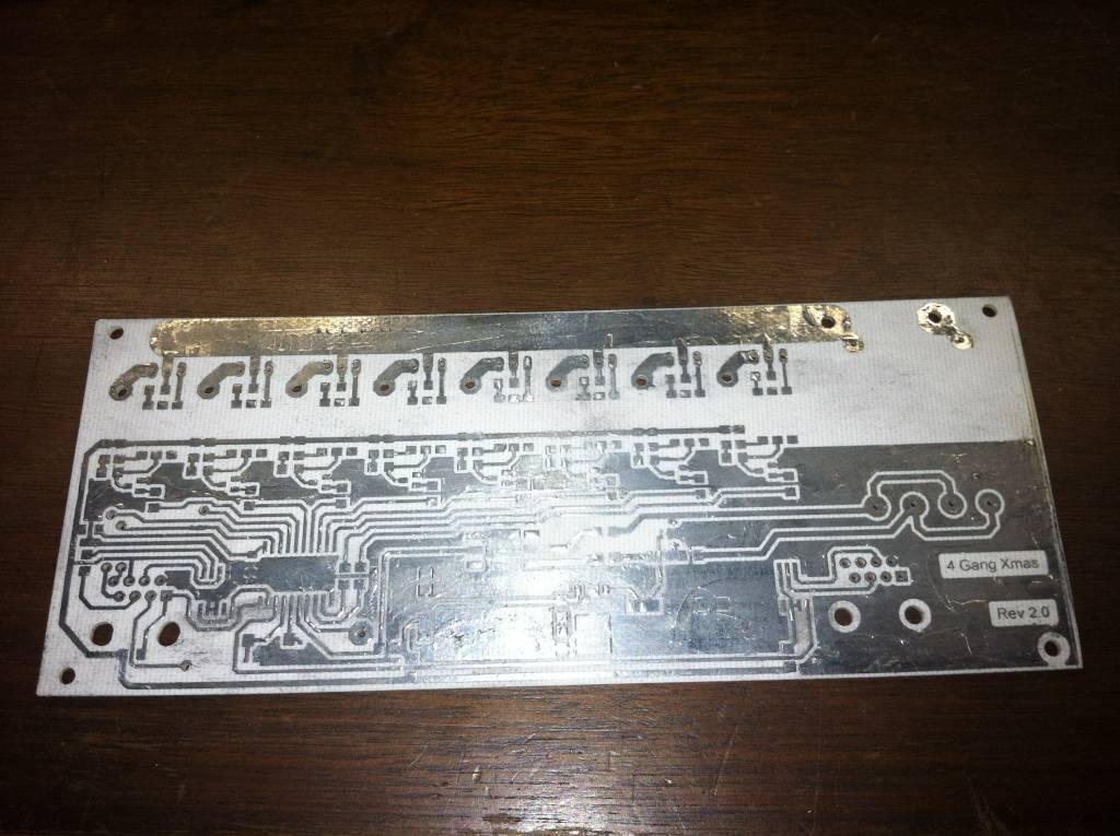
I designed and etched the 1st board by hand. I wasn't real sure how many of these I was wanting to make, or if it would even work all that well. I etched the first board and tinned all the copper to protect it from corrosion.
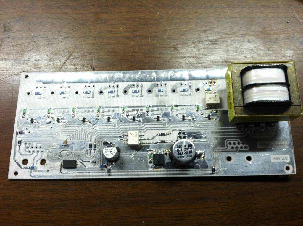
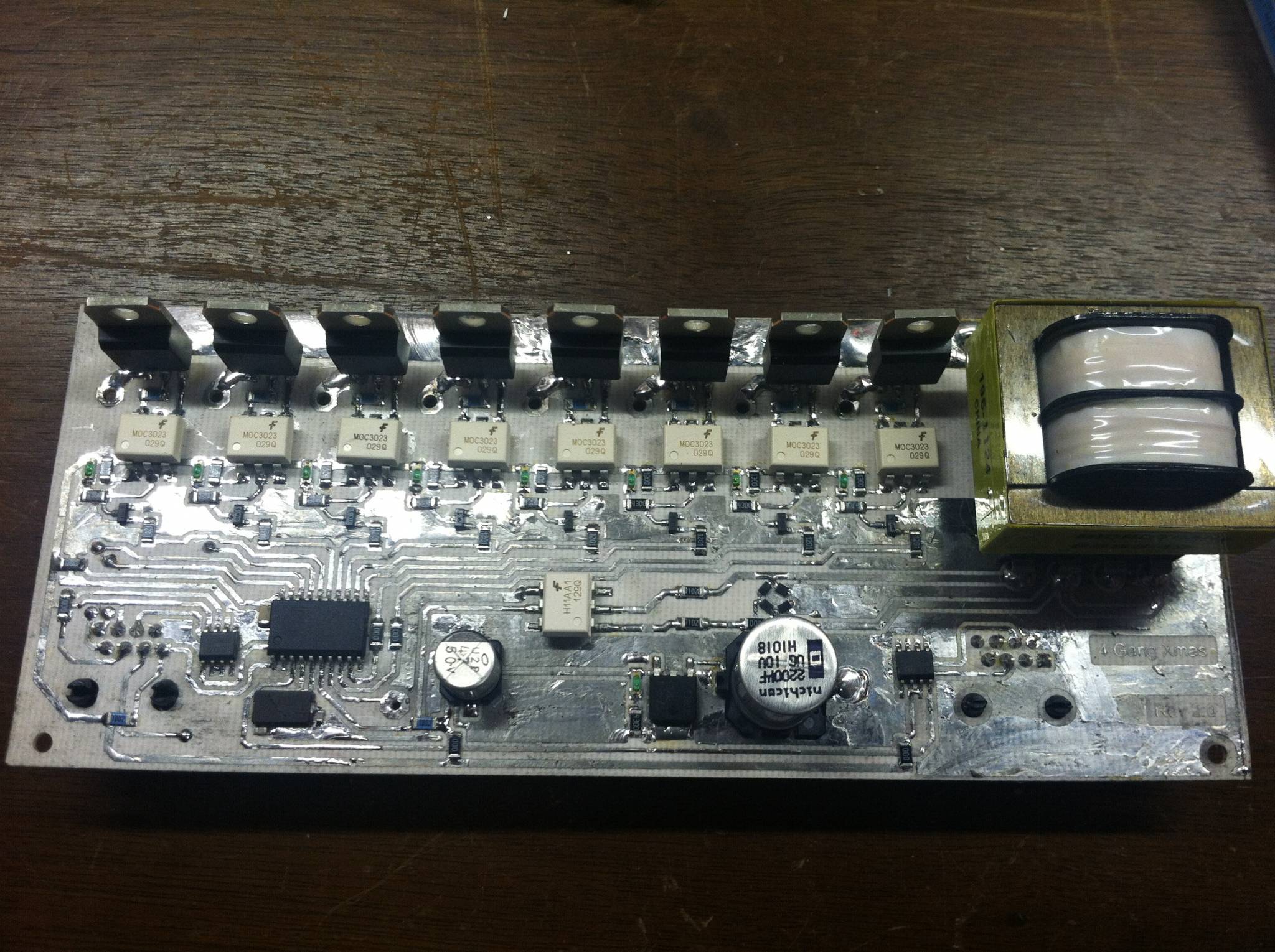
It's a combination of thru-hole and surface mount (SMD) components. I wanted to keep the hole count down as low as possible to make it easier to make. Also using SMD components, I could keep the board small enough to fit inside. The integrated power supply would provide power to the logic circuit while the back side would still provide the 120v needed for the Christmas lights.
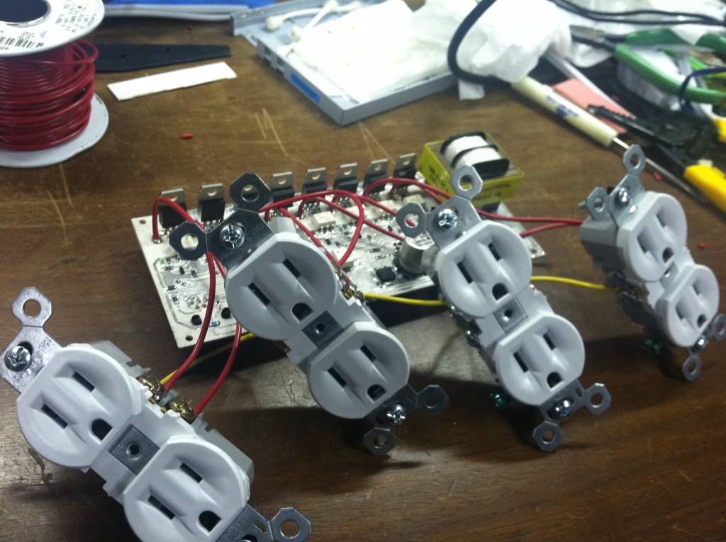
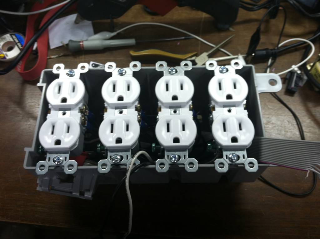
Once the board was completed, it was time to connect some outlets. each outlet tab on the side was broken off effectively making each outlet its own circuit. Only the hot side of the outlet was separated, the neutral side i left intact.
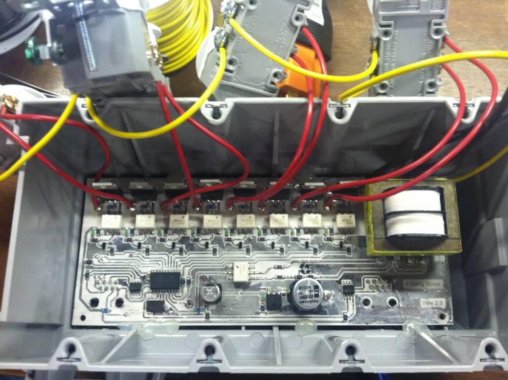
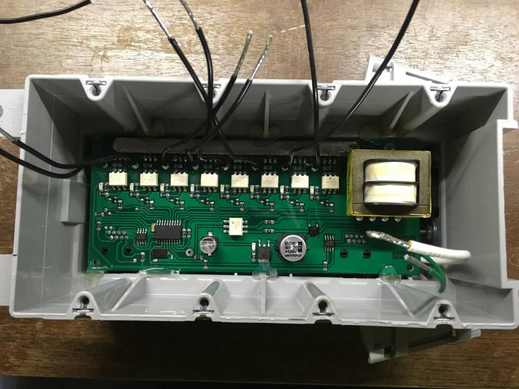
Mounting the board into the box was done real scientific like. Yup, hot melt glue. Turns out that stuff works really well. Later on when I wound up taking this apart to redo the wiring a little but, I found out how well it worked. The board was sized to fit in the box at this position. This gives just enough room from the outlets to be mounted over top, with some space underneath. This first version I did with the triacs on the trace side of the board. Everyone after that I faced the triacs downwards as there was plenty of room to do so. This also allows space to heatsink them in the future if I deem it needed. So far, they work just fine without. That's with pushing 3 100 light strands of light off of one.
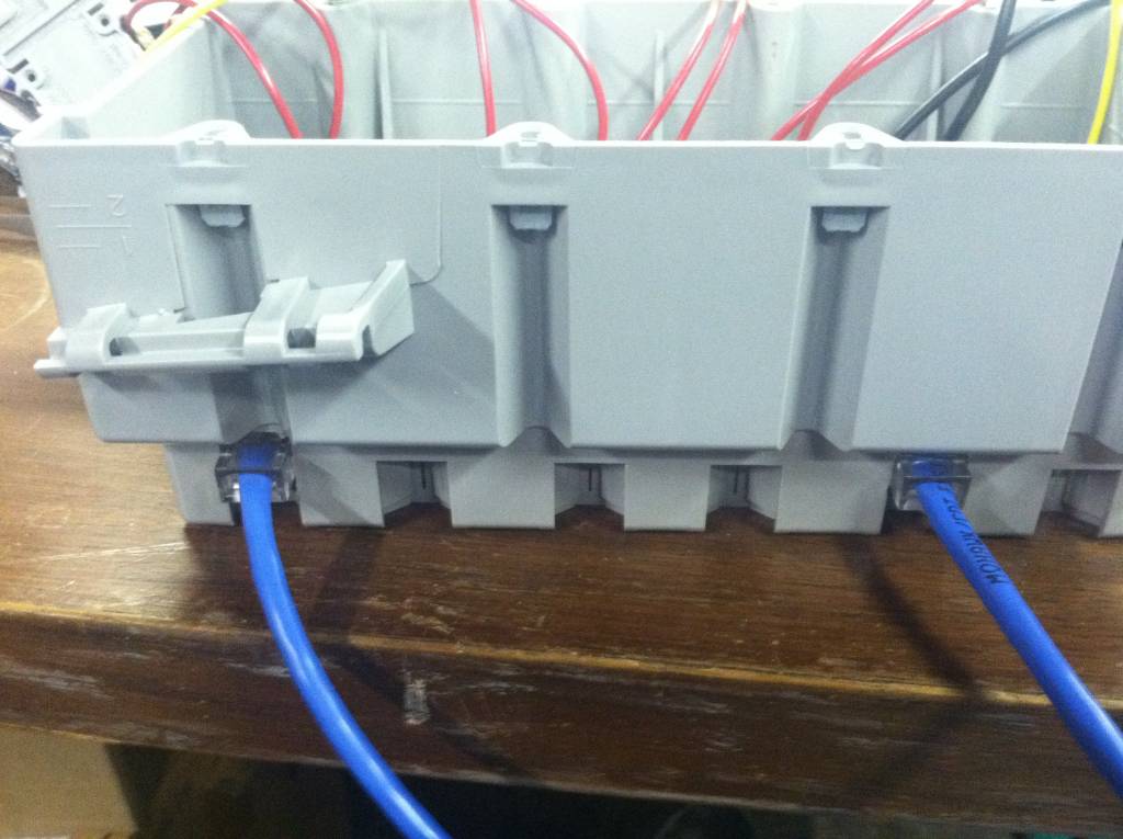
On the bottom of the board 2 rj-45 jacks are soldered on the board. The one on the left serves two purposes: a programming port, and a data stream port. The 2nd port is a pass-thru or re-transmit port. Yes these boxes were designed to be daisy chained together. I really don't know what the limit is. its a rs-485 data bus, but instead of being a node on a pair of wires, each box basically intercepts the data and re-transmits what its not for it. So basically between each box is a new rs-485 bus. The only limit right now is the firmware on the boxes would only allow for 256 boxes to be connected. I haven't seen a need to change that yet.
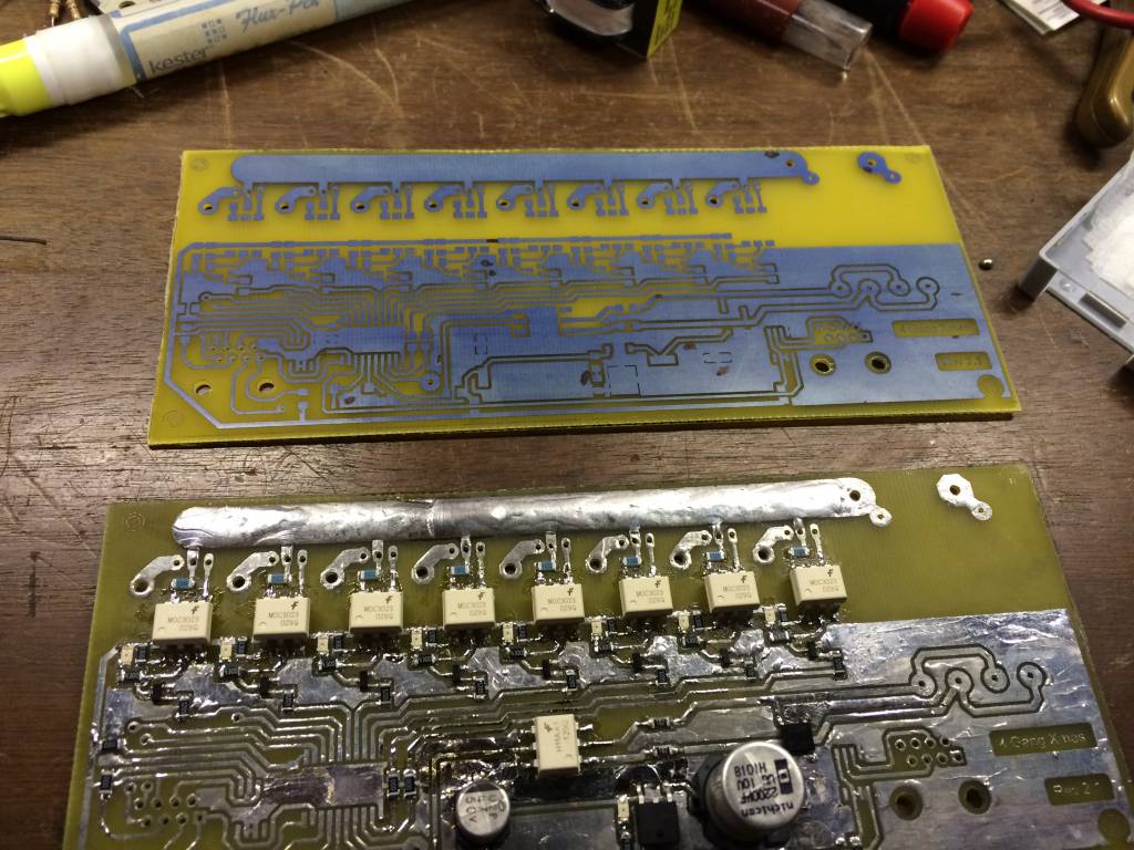
Here's what it looks from when I first etch the board to being soldered up and ready to test. Yest I have been using the toner transfer method for all of these. 3 have been built this way.
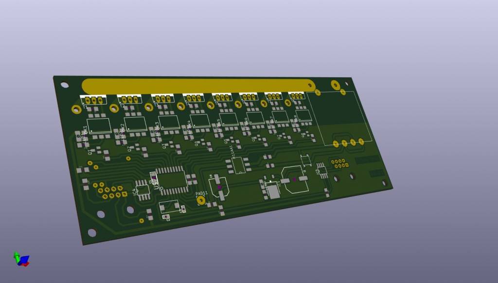
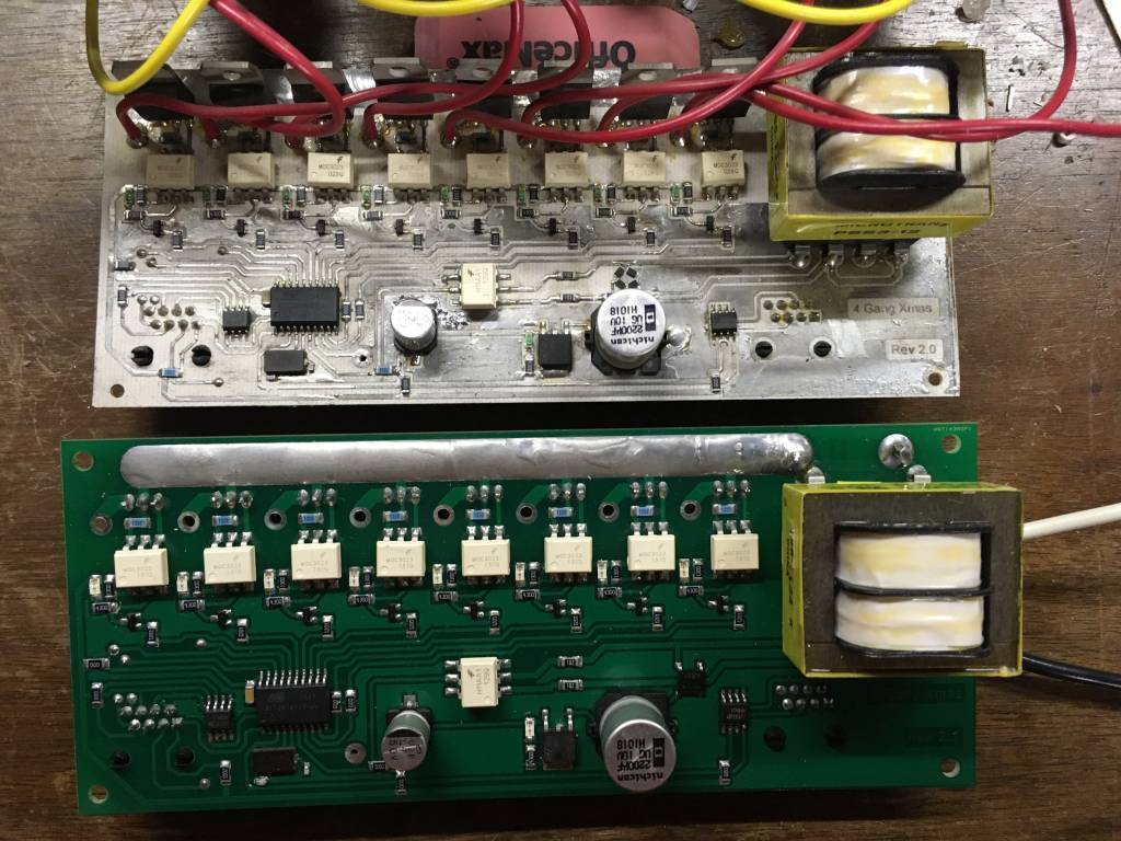
After having a few in use, and showing to be a great success in working, it was time to just get the boards manufactured. Prices on PCB manufacturing have come way down over the years. I converted over to KiCad for my EDA, made a small tweak to the board and sent off the gerber files to the fab shop. About 2-3 weeks later, i have a nice batch of 10 shiny new boards.
The new boards were much easier to solder with having the solder mask on then. And makde this project look a lot better to boot. Granted you don't ever really see the boards once they are mounted inside the box, but I know what it looks like.
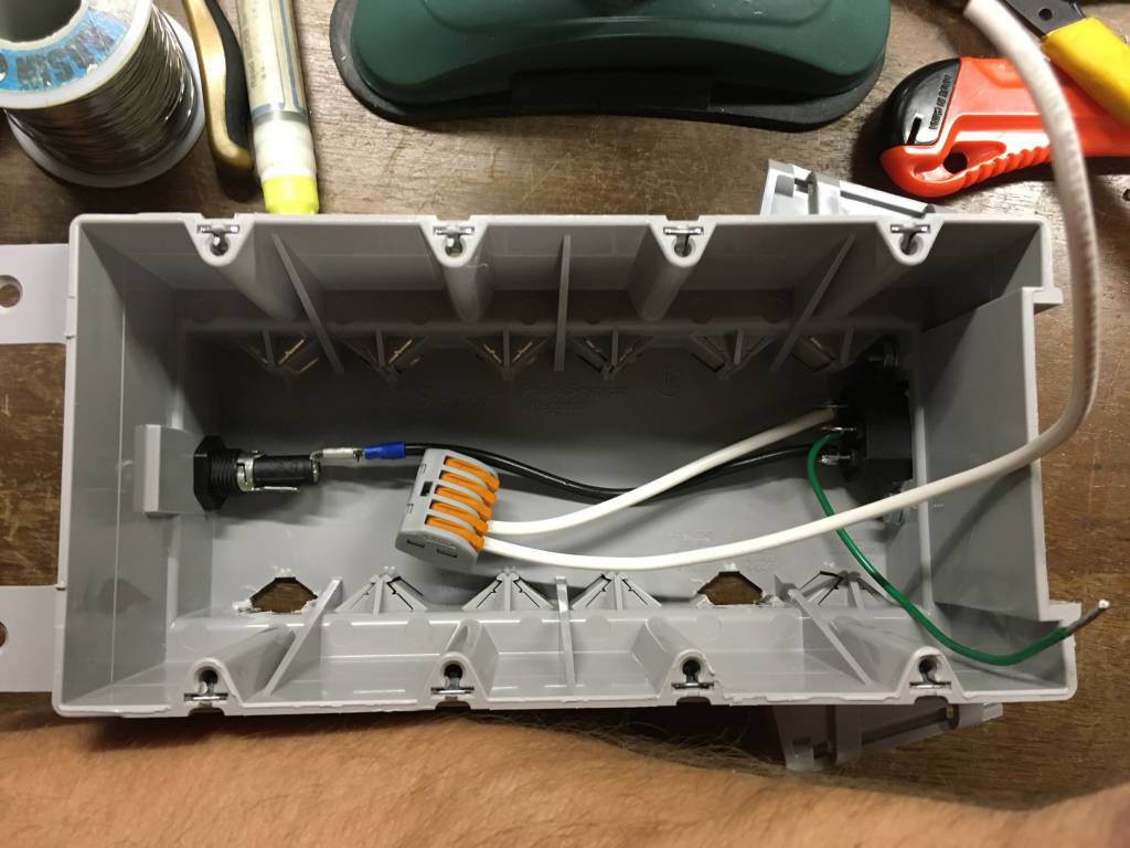
Before when testing, i Just soldered a power cord to the PCB and ran it out next to the outlet. Worked fine at the time, but I wanted to close them up, make them a little safer, and better looking. Mounting an IDC power connector in the side of the box allowed for a detachable power cord, and a cleaner look. Even added a fuse holder to add to the safety incase anything were to go wrong.. Split the neutral because one was needed for the circuit board, and one was needed to connect to the outlets themselves.. The hot line just connects directly to the circuit board right off the fuse holder (wire not shown).
The fabricated boards look so much better. You can see the neutral wire and the outlet ground wire coming out from around the side to connect to the outlets. The black wires are the switched hots that will connect to the outlets.
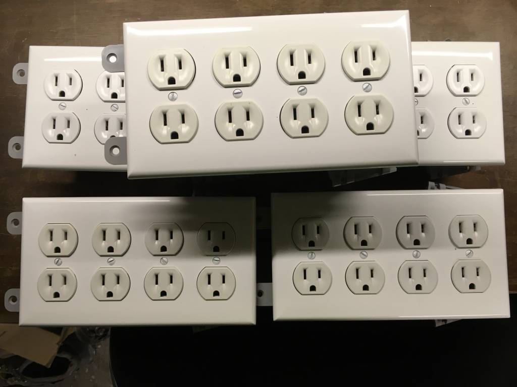
So all said and done, I now have 5 fully functional boxes to connect for a total of 40 individual addressable channels. I have enough boards and components to make 8 more yet. Usually about once a year around the holidays, I will sit down and make one or two more.
In the future, I might get into the code and share how it works. It's actually pretty simple. Each year it gets a go over and bugs fixed and features added.